- Published 20 Dec 2024
- Last Modified 20 Dec 2024
- 8 min
A Complete Guide to Insulation Resistance & IR Testing
This article explains insulation resistance, its importance, testing procedures, and how to interpret results for electrical safety and performance.

What is Insulation Resistance?
Insulation resistance refers to the ability of an insulating material to prevent the flow of electric current, ensuring that electricity only travels through the intended conductors. It’s vital for the safety and efficiency of electrical systems, as low insulation resistance can lead to dangerous leakage currents, electrical shocks, or equipment damage.
Maintaining proper insulation resistance is crucial, and conducting regular tests helps identify issues before they become serious. Common mistakes include using incorrect testing voltages or overlooking environmental factors, such as moisture, can compromise results and safety.
What is Insulation Resistance Testing?
Insulation resistance (IR) testing is a critical procedure used to evaluate the effectiveness of insulation in preventing electrical leakage. This test involves applying a high voltage to an electrical system and measuring the resistance using a device called a megohmmeter. The test checks whether the insulation is intact and able to resist the flow of current, helping to identify potential risks before they lead to serious issues.
The primary objectives of insulation resistance testing are to detect insulation deterioration, ensure electrical safety, and prevent hazards. As insulation ages or is exposed to harsh conditions, its resistance decreases, which could lead to electrical failures, fires, or electric shocks. Regular testing helps identify these issues early, reducing the risk of accidents and equipment damage. In Australian industries such as construction, mining, and manufacturing, insulation resistance testing plays a vital role in maintaining system reliability and protecting workers and equipment.
Insulation Resistance Degradation
Insulation resistance degradation refers to the weakening of insulating materials over time due to factors like moisture, temperature changes, and physical wear. As the insulation deteriorates, it becomes less effective at preventing electrical leakage. This degradation can pose significant risks, including electrical faults, equipment failures, and safety hazards. Regular insulation resistance testing is essential to detect these issues early, ensuring the system remains safe and functional.
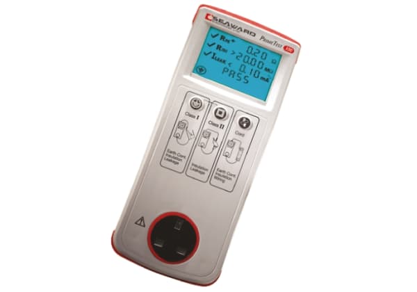
PAT Continuity: Testing Insulation Resistance For Electrical Equipment
Continuity testing is crucial for ensuring that electrical circuits are complete and capable of conducting current safely. By verifying that there are no breaks or gaps in the wiring, it helps ensure the safe operation of electrical systems. However, in addition to continuity, insulation resistance testing is equally important. It checks the condition of the insulation around electrical wires and components, detecting any faults or potential risks that could lead to electrical leakage, short circuits, or other hazards.
Insulation resistance testing is used to evaluate whether the insulating material effectively prevents current from escaping, ensuring that electrical equipment operates as intended without posing safety risks. In environments where electrical systems are frequently used, such as construction sites, this testing becomes even more critical. Over time, environmental factors, wear, or exposure to harsh conditions can degrade insulation, increasing the risk of accidents. Regular testing helps identify any weaknesses in insulation before they lead to serious hazards.
In Australia, where safety standards are strictly enforced, conducting IR tests regularly is essential for compliance and for maintaining a safe working environment. They play a key role in preventing electrical fires, shocks, and equipment failures, ensuring safety in high-risk industries such as mining, manufacturing, and construction.
PAT Continuity Results
Interpreting the results of continuity and insulation resistance tests is crucial in ensuring the safety of electrical appliances. A low reading on a continuity test typically indicates a break or fault in the wiring, meaning the circuit is incomplete, and the appliance may not function properly. Similarly, a low reading on an insulation resistance test suggests that the insulation is deteriorating, potentially allowing electrical current to leak, which poses a safety hazard.
When an appliance fails either test, immediate action is required. First, the appliance should be taken out of service and clearly tagged as “faulty” to prevent accidental use. Next, a qualified technician should assess the appliance to determine whether it can be repaired. If repair is possible, the appliance should be re-tested for both continuity and insulation resistance to ensure it meets safety standards. If the appliance is beyond repair, it should be safely disposed of in accordance with regulations.
In Australia, strict regulations govern the handling of failed appliances. According to workplace safety standards, failed equipment must be tagged and removed from service until repairs are completed and re-testing confirms it is safe for use again. These steps ensure compliance with safety standards and protect workers from electrical hazards.
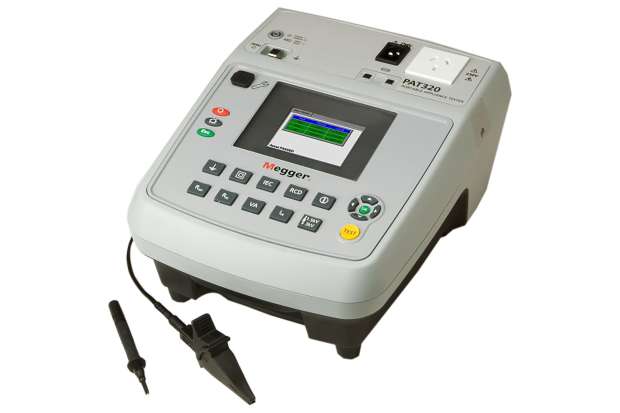
Related Testing Equippment
Insulation Resistance Testing Procedure
Insulation resistance testing is an essential part of routine electrical maintenance, helping to ensure the safety and reliability of electrical systems. It involves assessing the ability of the insulation in equipment to prevent current leakage, thereby preventing electrical hazards.
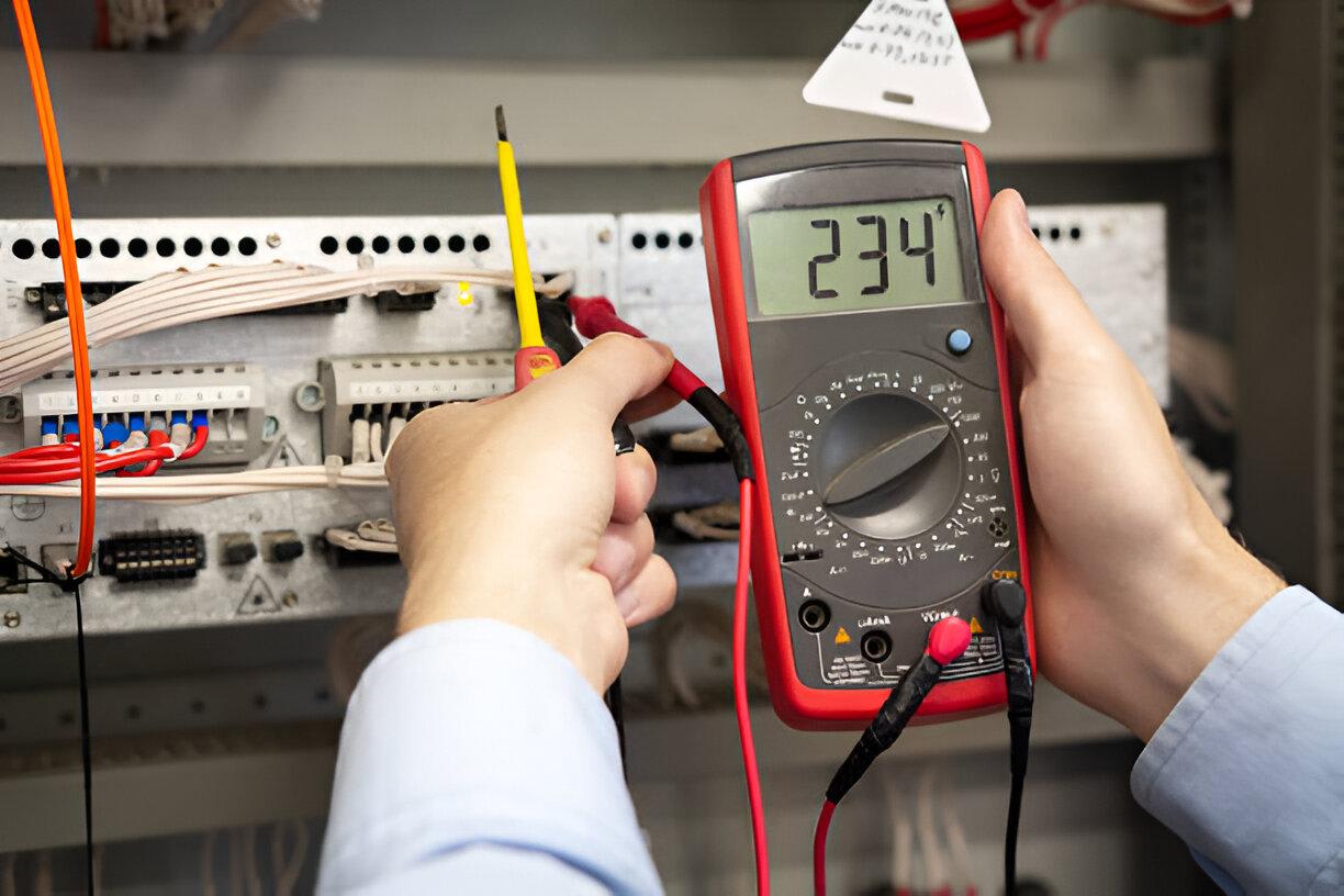
How to Test Insulation Resistance?
Before starting the test, it’s important to establish a safe workspace. This includes following isolation procedures and utilizing tag-out and lock-out systems to ensure that no live current is present in the system. Verify that the insulation resistance tester is properly calibrated according to manufacturer instructions.
- Pre-test Continuity Check: Ensure no live current is present by testing for continuity in the circuit.
- Connecting the Tester: Attach the tester leads to the equipment, ensuring they make secure contact with the insulation.
- Selecting the Test Voltage: Choose an appropriate test voltage (e.g., 500V or 1000V) based on the equipment type and the condition of the insulation.
- Observing and Recording Readings: Apply the test voltage gradually and observe the resistance readings. Record the results for further analysis.
During testing, handling high-voltage equipment requires caution. Wear proper PPE, including gloves and insulated tools, to meet Australian safety standards. Be aware of potential hazards such as electric shock and avoid common mistakes like inadequate lead connections or using the wrong voltage.
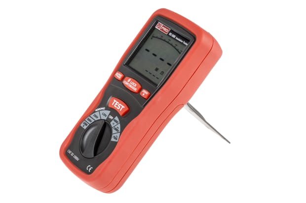
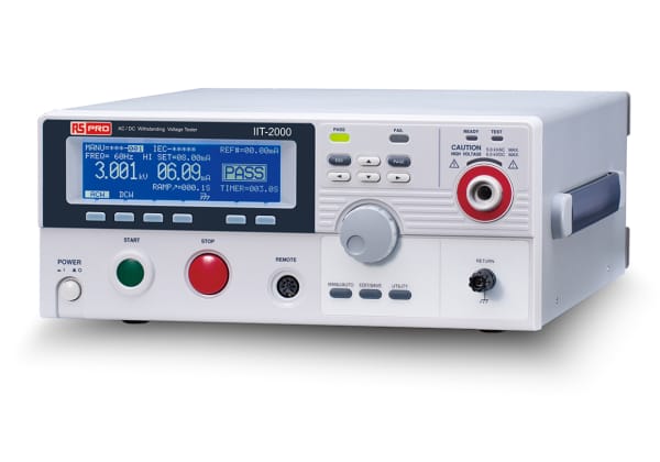
Using Insulation Testers (Megohmmeters)
Insulation testers, also known as megohmmeters are designed to measure the resistance of insulation by applying a high voltage. Unlike a multimeter, which measures lower resistances, a megohmmeter uses higher voltages (500V, 1000V, or more) to test insulation. The voltage chosen depends on the type of equipment and its operational environment. A higher voltage is typically used for systems with stronger insulation, ensuring the material can withstand operational stress without failure.
IEC Standard for Insulation Resistance Testing
The IEC standard for insulation resistance testing, IEC 60270, provides essential guidelines for measuring insulation resistance in electrical systems and equipment. This standard ensures uniform testing procedures, allowing for accurate measurements and consistent assessment of insulation quality. It specifies test equipment, voltage levels, and acceptable resistance thresholds based on the type and environment of electrical systems.
In Australia, the equivalent standard is AS/NZS 3760:2010, which governs the in-service safety inspection and testing of electrical equipment. Both IEC 60270 and AS/NZS 3760 emphasize the importance of regular insulation resistance testing to detect degradation, moisture ingress, and other factors that could lead to safety hazards, ensuring ongoing electrical safety and reliability.
Insulation Resistance Test Results
Insulation resistance test results are often evaluated using ratios like the Dielectric Absorption Ratio (DAR) and the Polarization Index (PI), which provide a deeper understanding of insulation health over time.
Dielectric Absorption Ratio (DAR): The DAR compares the resistance measured at 1 minute to that at 30 seconds. A DAR below 1.25 indicates questionable insulation, while a range of 1.25 to 1.60 is considered good, and anything above 1.60 is excellent.
Polarization Index (PI): The PI compares resistance at 10 minutes to that at 1 minute. A PI below 1.0 signifies poor insulation, while values above 4.0 are deemed excellent.
In Australia, the standard AS/NZS 3000:2007 specifies that insulation resistance must be tested using a 500V or 1000V tester, with a minimum resistance of 1 megaohm between live conductors and earth, and 10,000 ohms for low voltage equipment like stoves and water heaters. Furthermore, during the test, the total current, comprising leakage, absorption, and capacitive currents, changes as the test progresses. Initially, leakage current decreases, while absorption and capacitive currents stabilize, providing a clearer picture of insulation quality and helping technicians assess potential risks.
Understanding Different Current Types in Insulation Test
In insulation resistance testing, understanding how different types of current behave is crucial for assessing the health of insulation. By analyzing these currents, technicians can detect potential issues, such as insulation degradation or contamination, which could pose safety risks.
Leakage Current
Leakage current refers to the small amount of electrical current that flows through or along the surface of the insulation material. This current typically occurs due to contamination, moisture, or physical damage in the insulation. High leakage currents may indicate that the insulation is deteriorating, creating a potential safety hazard, as the insulation may no longer effectively contain the electrical current. In some cases, persistent leakage current is a clear signal that the insulation requires repair or replacement.
Absorption Current
Absorption current is the current that flows as the insulation material “charges” during the test. Initially, the current is higher and gradually decreases as the insulation material absorbs the charge, stabilizing over time. This pattern helps differentiate between good and deteriorating insulation, with poor insulation often showing slower stabilization. The Polarization Index (PI) test, which compares resistance values at different times, is particularly useful for evaluating absorption current and assessing insulation health.
Capacitive Current
Capacitive current is the current that arises due to the capacitive properties of the insulation. This current occurs only during the initial stage of the test when the insulation is charging. It diminishes quickly and is generally ignored in steady-state measurements, as it does not indicate the condition of the insulation once the system is fully charged.
Total Current
Total current is the sum of leakage, absorption, and capacitive currents during the insulation test. Monitoring this total current over time offers insights into the overall health of the insulation. For example, if leakage current remains steady but absorption current decreases, it may suggest moisture ingress or contamination in the insulation. Understanding how these currents change over time can help identify and address insulation issues early.
Importance in Interpreting Insulation Resistance Test Results
Distinguishing between different current types is essential for interpreting insulation resistance test results. For example, high leakage current in the steady-state can indicate moisture or contamination, while a slow drop in absorption current could signal aging insulation. Technicians can use these insights to identify specific insulation issues. Following testing standards, such as those set by AS/NZS 3000:2007 and IEC 60270, is critical to ensure accurate interpretation and effective maintenance of electrical systems.