- Published 30 Oct 2026
- Last Modified 30 Oct 2026
- 10 min
Function Generators Explained: What They Do, How They Work & Their Uses
This practical guide explains what function generators do, how analogue and Direct Digital Synthesis (DDS) architectures operate, their primary circuit-testing applications, and key specifications to consider when selecting an instrument.


A function generator is test equipment that produces repeating electrical waveforms, such as sine, square and triangle waves, at a frequency you set. Engineers and students feed that known signal into a circuit to see how it responds, which makes the instrument a regular fixture on electronics benches and in teaching labs.
This guide covers what a function generator does, how it works, the main types and uses, and how to use one, followed by its limitations and the specifications to check before you choose a model.
What Is a Function Generator?
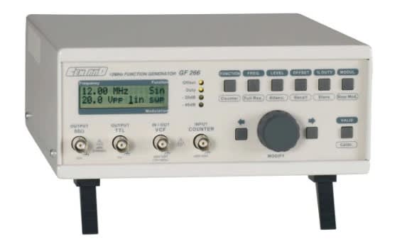
A function generator is an electronic instrument that creates repeating electrical waveforms of a chosen shape, frequency and amplitude. In electronics, it gives a circuit a known test signal, so you can measure exactly what happens when that signal is applied.
As a type of signal generator, it belongs to a broader family of instruments that produce test signals of a known frequency and shape. Function generators cover the general-purpose end of that family, with common waveforms at low to moderate frequencies, whereas RF signal generators reach higher frequencies and arbitrary waveform generators produce custom shapes.
In a typical electronics lab or repair workshop, a function generator works alongside three other instruments. Oscilloscopes display and measure signals, multimeters check voltage, current and resistance at test points, and a power supply provides the DC power that the circuit under test needs. The function generator supplies the input signal, so power, stimulus and measurement are all covered.
What Does a Function Generator Do?
A function generator produces a stable, repeating electrical signal of a shape, frequency and amplitude you choose. Its purpose is to give a circuit a known, repeatable input, so you can see what the circuit does with it each time.
Most models offer five standard waveforms:
- Sine: smooth wave used for audio and frequency response tests
- Square: fast on-off wave used as a clock or logic test signal
- Triangle: linear rise and fall used to check amplifier linearity
- Sawtooth (Ramp): slow rise and sharp drop used for scanning and timing circuits
- Pulse: short pulses with adjustable width used for digital and trigger tests
Four main controls shape the output:
- Frequency: how many cycles the waveform repeats each second
- Amplitude: the height of the waveform, which sets the signal level
- DC Offset: a fixed voltage that shifts the whole waveform up or down
- Duty Cycle: the share of each cycle that a square or pulse wave stays high
Because the signal is identical every cycle, any change you see at the output comes from the circuit and not from the input.
How Does a Function Generator Work?
A function generator works by building a waveform inside the instrument and delivering it to the output at the amplitude and frequency you set. Analogue models create the shape with electronic circuits, whereas digital models calculate it from stored values and convert those values into a voltage.
Analogue Method
An analogue generator charges and discharges a capacitor with a constant current, which produces a triangle wave. Shaping circuits then convert that triangle into square and sine waves, and an output stage sets the signal level at the socket. The approach is simple, but frequency settings are less precise and drift more with temperature.
Direct Digital Synthesis (DDS)
Direct digital synthesis (DDS) builds the waveform from numbers instead. A phase accumulator steps through each cycle at a rate set by the chosen frequency, a waveform look-up table converts each step into a value, and a digital-to-analogue converter (DAC) turns those values into a voltage. A filter then smooths the result before the output stage.
Changing the frequency only changes how fast the accumulator steps, so the generator can switch frequency quickly without rebuilding the stored waveform. For that reason, most modern function generators use DDS.

Types of Function Generator
The main types of function generator differ in how they create the signal and how freely you can shape it. A standard function generator outputs a limited set of predefined periodic waveforms. An arbitrary function generator (AFG) adds memory for a waveform you define, and an arbitrary waveform generator (AWG) plays back large, complex or sequenced waveforms from memory.
Analogue Function Generators
Analogue models use oscillator and shaping circuits. They suit simple tests and teaching, though frequency accuracy and resolution are lower than on digital models.
Digital (DDS) Function Generators
Digital models use DDS to synthesise waveforms from stored values, so frequency is precise and changes quickly. They suit most general bench work.
Arbitrary Function Generators (AFG)
An AFG keeps the fast frequency changes of DDS and adds memory for a waveform you define. It suits users who need standard shapes plus an occasional custom signal, such as a recorded sensor output.
Arbitrary Waveform Generators (AWG)
An arbitrary waveform generator plays stored points back in order, so it can produce nearly any waveform you can define, including sequences with loops and triggers. It gives up the quick frequency changes of DDS for that freedom, and it suits complex signals for wireless and optical testing.
Sweep Function Generators
A sweep function generator moves its output frequency from a start value to a stop value over a set time. It suits filter and frequency response tests, where one sweep replaces many manual changes.
Form factors include benchtop units, handheld instruments, USB modules and generators built into oscilloscopes.
What Are Function Generators Used For?
What a function generator is used for comes down to one application: supplying a controlled signal to a circuit and observing its response. The use of a function generator ranges from fault finding on a repair bench to teaching in a university lab.
Circuit Testing and Troubleshooting
Tracing a known input signal through each stage shows where a circuit loses, distorts or blocks it. A sine wave reveals gain loss and clipping, whereas a square wave exposes slow edges and ringing.
Filter and Frequency Response Testing
Stepping or sweeping the frequency through a filter or amplifier while measuring the output reveals its cut-off point, usually where the level falls 3 dB below the passband. Filters built from passive components such as resistors and capacitors are a common example.
Clock and Timing Signals
A square wave can stand in for a clock or trigger when testing digital logic and microcontroller circuits, with frequency and duty cycle set by hand. Match the amplitude and offset to the logic family’s levels, such as 0 V to 3.3 V.
Sensor Simulation
A generator can imitate a sensor output, such as a slow sine wave or a pulse train from a speed sensor, so the reading software can be tested without the real device. A small amplitude with a DC offset reproduces the low-level, biased signals many sensors produce.
Audio Equipment Testing
Sine waves across the audio range (roughly 20 Hz to 20 kHz) test amplifiers, speakers and mixers for gain and distortion, and a sweep shows the frequency response. A 1 kHz sine wave is the usual reference tone.
Education and Training Labs
Students pair a function generator with an oscilloscope to see how waveforms, filters and circuits behave, which makes abstract theory visible. Typical exercises include plotting an RC filter’s frequency response and measuring square-wave rise time.
How Do You Use a Function Generator?
Using a function generator takes five steps: connect the output, set the load, choose the waveform and frequency, set the amplitude and offset, then enable the output and verify it on an oscilloscope. Check each setting before moving on, because a wrong load or amplitude changes what the circuit actually receives.
Step 1: Connect the Output to the Circuit
Run a coaxial lead, usually fitted with BNC connectors, from the generator output to the circuit input, and join the grounds. Keep the output switched off while connecting.
Step 2: Set the Output Load
Set the load to 50 ohm or High Z (high impedance) to match the circuit input, because the setting changes the real amplitude. A generator set to 50 ohm but feeding a high impedance input delivers about double the displayed level.
Step 3: Choose the Waveform and Frequency
Select sine, square, triangle, ramp or pulse, then enter the frequency the test needs.
Step 4: Set the Amplitude and DC Offset
Set the amplitude so the signal stays within the circuit's safe input range. Add DC offset only when the circuit needs the signal to sit above zero volts.
Step 5: Enable the Output and Check It on an Oscilloscope
Switch the output on, then view the signal on an oscilloscope to confirm the shape, frequency and amplitude match your settings. Adjust the controls if they do not.
What Is the Difference Between an Oscilloscope and a Function Generator?

A function generator creates an electrical signal, whereas an oscilloscope displays and measures an electrical signal. The generator drives the input of a circuit, and the oscilloscope shows the waveform at any point you probe, including its shape, frequency and amplitude.
The two instruments are usually used together, with the oscilloscope verifying both the generator output and the circuit response. Neither replaces the other, because a generator cannot measure a waveform and an oscilloscope cannot create a repeatable test signal. Some oscilloscopes include a built-in generator, which suits compact benches and teaching labs where one instrument must do both jobs.
What Are the Limitations of Using a Function Generator?
A function generator is limited by its maximum frequency, the fixed set of waveforms on basic models and its low output current. Each limit affects what you can test, so check all three against your circuit before you rely on the instrument.
- Maximum Frequency: Square-wave edges become slower and sine waves less pure as the output approaches the frequency limit, so leave comfortable headroom.
- Fixed Waveforms: A basic model offers only its built-in shapes, and custom waveforms need an arbitrary function generator or arbitrary waveform generator.
- Output Current: The output suits signal inputs but cannot drive loads that draw real power, because a function generator is not a power supply.
For heavier loads, add an amplifier stage or power the load from a separate supply.
How to Choose a Function Generator
Choose a function generator by matching eight specifications to the work it will do:
- Maximum Frequency: Pick a limit comfortably above the highest frequency your circuits use.
- Number of Channels: Choose two channels when you need related signals at once, such as a signal and its clock.
- Sample Rate and Resolution: Higher values give smoother, more accurate waveforms, which matters most for arbitrary shapes.
- Arbitrary Waveform Support: Choose an arbitrary function generator if you need custom shapes beyond the standard set.
- Modulation and Sweep: Check for amplitude, frequency and phase modulation, and for sweep if you test filters or communications circuits.
- Amplitude Range: Confirm the range covers both small sensor-level signals and the larger levels your circuits need.
- PC Connection: USB or network control allows remote operation, waveform upload and automated testing.
- Form Factor: Benchtop units suit labs, handheld units suit fieldwork, and USB or oscilloscope-integrated units save space.
Function Generator FAQs
Function Generators at RS Australia
RS Australia supplies function generators and arbitrary waveform generators, including options from brands such as Aim-TTI, IKALOGIC and RS PRO.
Whether you need a simple bench unit or an arbitrary waveform generator for custom signals, you will find both in the range of function generators, part of the wider signal generators and analysers category. The same category includes RF signal generators for higher-frequency work and spectrum analysers for viewing signals by frequency.
Orders for eligible Australian stock placed before 5pm AEST on a business day qualify for next-working-day delivery, and free delivery applies for orders above their relevant minimum order values. For more details on current thresholds and fees, please visit our delivery information page.
Further Readings

Oscilloscopes - A Complete Buying and User Guide
An oscilloscope guide designed to help you understand what oscilloscopes are, what they are used for, the types and brands available and how to use them.

How to Choose the Best Multimeters: Comprehensive Multimeter Recommendations
Find the best multimeters in Australia for your electrical measurement needs. Explore top-rated brands for electricians like Fluke, Keysight & RS PRO.

Ammeters - A Complete Guide
This ammeter buying guide explains everything you need to know about what an ammeter is, how to use them, and the different types that are available.